This Winter Project 3D Test Print
With the upcoming projects of printing structures like the Chapel in the Pines and an Ancestral Farmhouse I felt it necessary to test the 3D printing of a full structure.
Our Winter Project, which was laser cut and assembled in many scales, provided an example of a 3D structure to test print the structure.
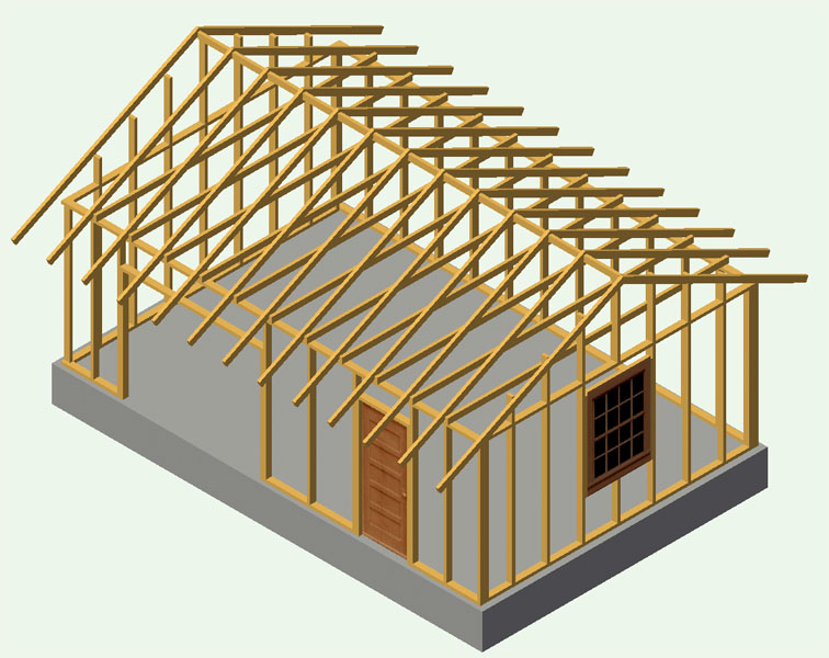
Here is the internal structure and door and window , less the overhead door, showing the 2X4s used in the construction. This drawing has a floor which I removed from the 3D drafting we will see below.
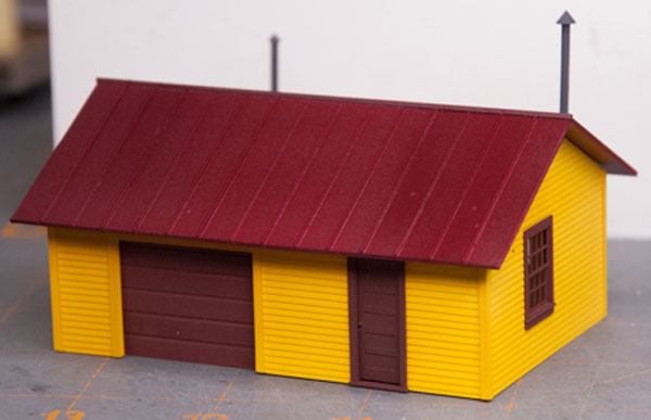
An example of the laser cut construction of the structure is shown in this image.
Laser cut Floor and rafters were installed on another model.
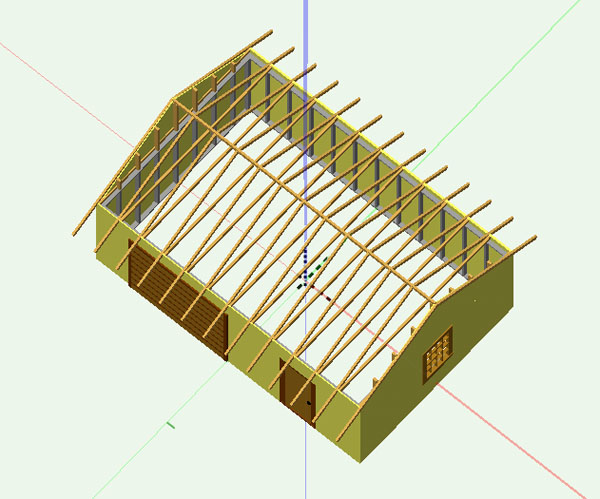
Moving to a 3D model for printing on the 3D printer required the generation of a full 3D drawing and then the scaling to HO scale (1:87.1) followed by generating a stereo Lithography (.stl) file for the 3D printer.
This drawing includes the internal and external elements of the structure less the floor and roof which were to be printed (or Laser cut ) separately.
Here is the representation of the .stl file from the above 3D drawing as shown in the Catalyst software used to operate the uPrint Printer in the Fab Lab. (Note there in no roof, ceiling or floor in this image)
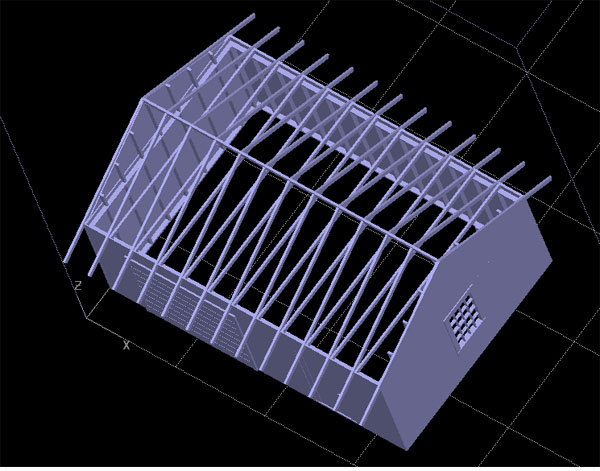
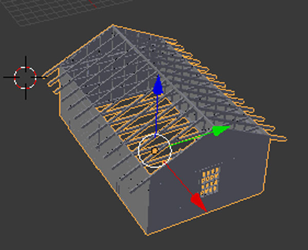
An additional test of the .stl file was entered into Blender to check for any errors. (Again no roof, ceiling or floor)
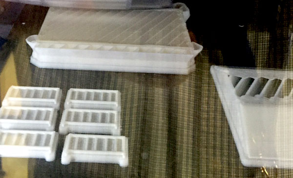
This is the printer starting the process of printing. Structure on top, roof is on the right.
The railings are for the Woodboro General Store.
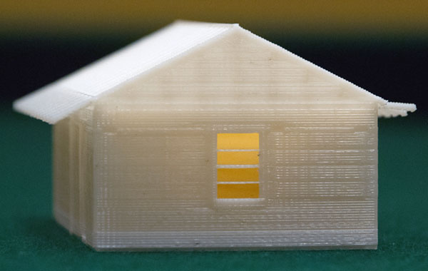
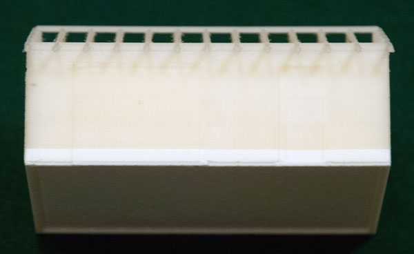
Here as a series of images of the finished print from the above .stl files.
The color and contrast of the material does not show much of the wall and end details. The change in color was due to the printer running out of white material and replacing it with Ivory colored material.
The structure seemed to weigh a considerably more than the plan called for and it had to all appearances a floor and ceiling.
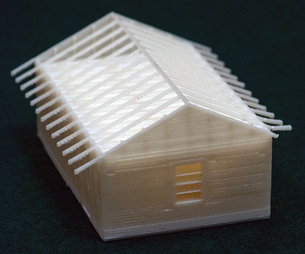
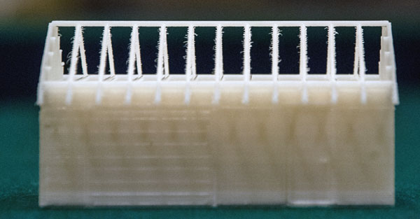
Upon careful inspection the 2X4s of the end walls show up as do the rafters however the vertical mullions of the window are missing. A look in the window showed that there were additional layers of material printed inside the structure.
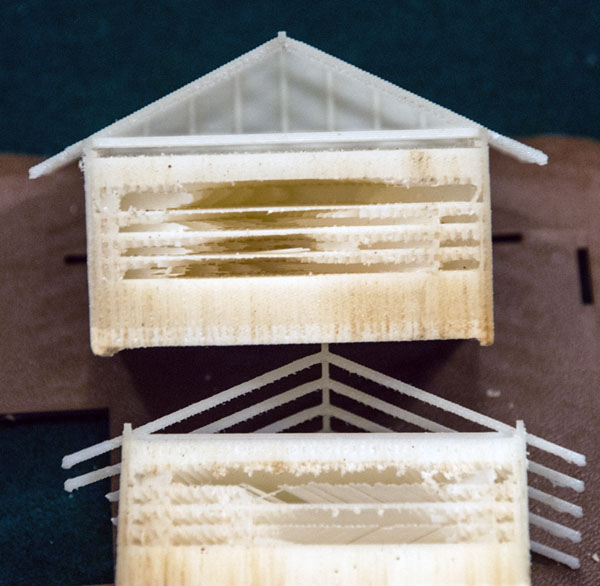
In order to investigate the issues seen here I used a band saw to slice the structure to get a view of the inside and how the printer used the .stl.
Here is a first look at the 2 parts of the structure after cutting. Some flash like materials were left by the saw and needed to be cleaned up. Again at the top we see that the studs and the beams and rafters were formed very well but we now see thick layers of structural material and some support material inside the structure.
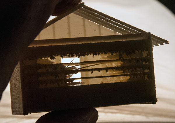
Here is a back lit view of the end with the window.
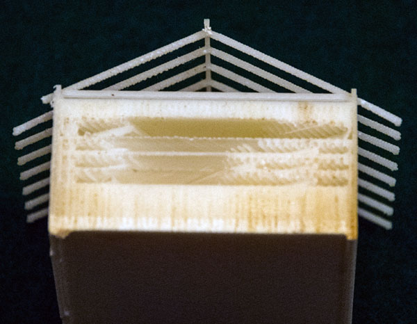
This image, of the other end, has been cleaned up and shows the printing material in 5 extra layers, .380" of floor, .010" or area of the lower window mullion, .020" behind the center horizontal window mullion, another .010" or area of the upper window mullion, and finial .180" above the window and below the horizontal roofing. There is also evidence of the filler material that is melted away left between these layers due to the lack of access via the window opening. (Tests show this to be filler that would be melted away)
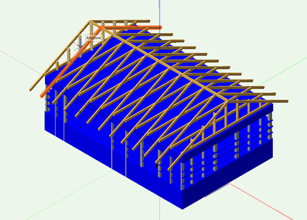
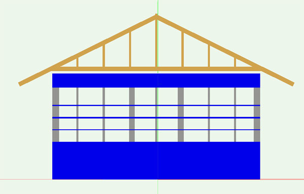
I did redraw the structure as built (without the walls) to show what was done in the printing. The blue material is not part of the structure and not in the .stl files and represents the extra material filling the structure.
This is a right isometric below is a right end.
At this time we have no understanding as to why the printer added so much material to the structure from an open drawing and well tested .stl
My personal recommendation, at this time, is to draw and 3D print the wall support structures (2X4s) as flat 3d prints and place laser cut walls on the printed studs.
While the roof structures are ok, laser cut HO scale beams work if done carefully.
How this reflects on other structures remains to be seen. The roof of this structure is a totally different story and will be covered on another page. (Click Here)
If you have ideas please contact me @ pwussow@gmail.com
Paul Wussow
Updated 8/31/15
Join us in the “Greatest Hobby” as a member of the TLMRC.


